Hardware Fundamentals
A server randomly reboots under load: is it the PSU, faulty RAM, or a thermal issue? A new workstation will not POST (Power-On Self-Test, the firmware’s initial hardware check that must succeed before the OS loads). A storage upgrade doubles cost but only marginally improves throughput because the bottleneck is elsewhere in the system. As a system administrator, these are the hardware situations that will land on your desk. You do not need to be a hardware engineer, but you do need enough understanding of how the components fit together to diagnose failures, spec appropriate machines, and have an informed conversation with vendors or your operations team.
Modern computers are built from a small set of well-defined parts that must match one another in socket, speed, and power budget. In this lecture you will learn how the motherboard, CPU, memory, storage, graphics card, power supply, and cooling fit together and what “compatibility” really means in practice. We will favor plain language first, then introduce the necessary terms (socket, chipset, PCIe lanes, TDP) with short glosses. By the end you should be able to read a spec sheet, choose parts that make sense for a given goal (a quiet student workstation, a home lab server, a cost-optimized cloud instance), and assemble a system that boots on the first try. Building on this foundation, later lectures on networking and operating systems assume you can reliably bring bare metal to life.
The Motherboard-CPU Platform
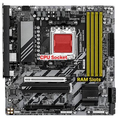
Section titled “The Motherboard-CPU Platform”Think of the motherboard as the city’s road grid and the central processing unit (CPU) as its central station: everything plugs into the board, and the CPU executes instructions. The motherboard is a large circuit board that connects all the main parts of a computer, providing a CPU socket (the physical interface for a specific processor family), a chipset (the set of controllers that expose expansion features), slots for memory (DIMM slots), storage connectors, and expansion slots. This platform choice creates the electrical and mechanical constraints every later decision must fit inside, so treating it as an integrated decision (CPU + board + memory generation) reduces downstream surprises.
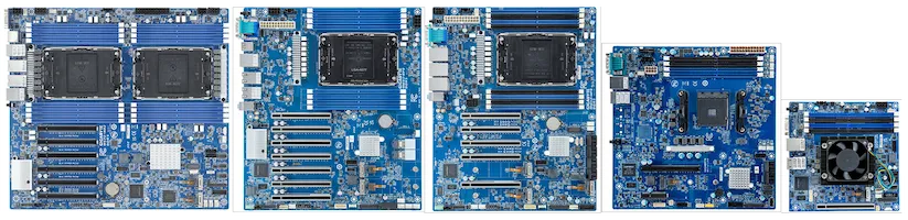
ATX is the most common motherboard size (form factor) for desktops, measuring about 12 x 9.6 inches. It matters because it determines how many slots and ports you get, and what cases will fit. Smaller sizes like microATX (mATX) and Mini-ITX offer fewer slots but fit in smaller cases. In 2025, many new boards support PCIe 5.0 for GPUs and at least one NVMe slot, with higher-end models more likely to offer a Gen5 NVMe slot for ultra-fast storage. ATX 3.x PSUs are increasingly recommended for high-wattage GPUs because they are designed for the large transient power spikes modern cards can demand.
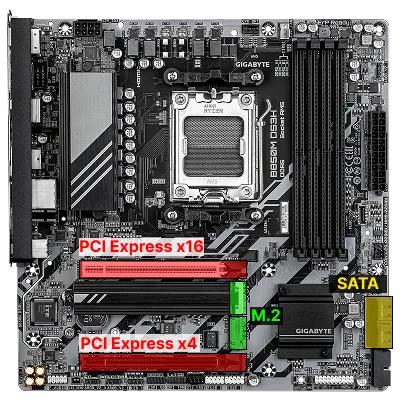
For storage, motherboards provide connectors like SATA (Serial ATA), a cable-based interface for hard drives and older SSDs, and M.2 slots for modern, stick-shaped drives. Some M.2 slots support NVMe (Non-Volatile Memory Express), a protocol that lets SSDs talk directly to the CPU over PCI Express (PCIe) lanes for much higher speeds than SATA. In 2025, PCIe 5.0 and Gen5 NVMe SSDs are increasingly common in higher-end consumer systems, offering up to about 14 GB/s sequential reads on PCIe 5.0 x4 drives, but they also require careful attention to cooling and lane allocation. PCIe is the main expansion bus for add-in cards like graphics cards (graphics processing units, or GPUs) and high-speed storage.
The CPU you choose locks in the socket and often the memory generation; for example, an “AM5” AMD CPU demands an AM5 board and DDR5 memory. Thermal Design Power (TDP) is a planning number for heat and power (not a strict cap), so cooling and power choices must assume real workloads. Some CPUs include integrated graphics for display output; if yours does not, a discrete GPU is required for video. Building on this platform is about matching the socket, chipset features, and physical layout to your goals and case size. A clear map of these relationships helps you reason about performance ceilings and upgrade paths. As platforms evolve, expect more features to move on-die (integrated into the CPU), and for new standards like PCIe 6.0 to appear on high-end boards first.
When selecting a platform, verify these before purchasing:
- Read the board’s CPU support list and memory Qualified Vendor List (QVL) before buying.
- Favor chipsets that expose the lanes and ports you will actually use.
- Confirm rear I/O you need (USB-C, 2.5/10GbE, Wi-Fi) and internal headers for your case.
- Check the manual for lane sharing rules between M.2, SATA, and PCIe slots.
Cases, Form Factors, and Physical Constraints
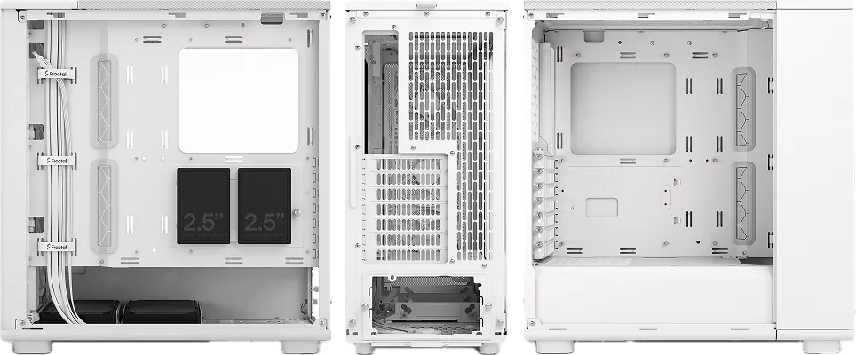
Section titled “Cases, Form Factors, and Physical Constraints”The enclosure (case) is more than aesthetics; it enforces the mechanical envelope for motherboard size, cooler height, GPU length, drive mounting, and cable routing that in turn affects thermals and noise.
ATX is not just a motherboard size: it is a standard that enforces the placement and dimensions of mounting holes, rear I/O shield cutouts, expansion slot alignment, and power connectors. This ensures that any ATX-compliant motherboard will fit in any ATX-compliant case, and that power supplies, expansion cards, and other components will line up correctly. ATX also defines the standard 24-pin power connector, rear I/O layout, and slot spacing, making it possible to mix and match parts from different vendors with confidence.
The name AT comes from IBM’s second-generation PC, the IBM PC/AT, where AT stands for “Advanced Technology.” ATX (Advanced Technology eXtended) is the modern, extended successor to the AT standard. In addition to physical dimensions and mounting, ATX standardizes the PSU rails presented to the board: +12 V, +5 V, +3.3 V, −12 V (mainly for legacy support), and +5 VSB (standby power, so components like the real-time clock remain active when the system is powered off). Modern motherboards then use onboard voltage regulators to derive the lower voltages actually used by the CPU, DRAM, chipset, and other components. The main board connector is 24-pin; an additional 4- or 8-pin EPS connector delivers a stable +12 V feed directly to the CPU power circuitry.
Common motherboard form factors, such as Extended ATX (E-ATX), ATX, microATX, and Mini-ITX, scale down slot count and header real estate as they shrink, so choosing smaller always trades expansion and sometimes ease of building for footprint.
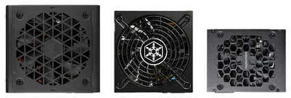
Power supply form factors (full ATX vs. SFX / SFX-L) influence internal volume and airflow paths, and cramped cases demand more deliberate cable management to avoid blocking front-to-back air.
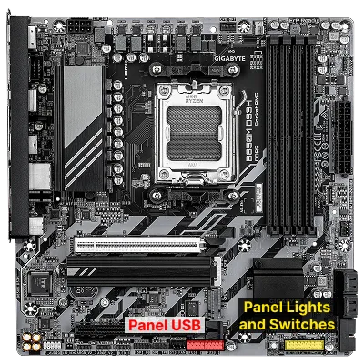
Front panel connectors (power/reset switches, LEDs, USB headers, audio) must be matched to the board’s pin layout; miswiring can cause mysterious no-boot or instant shutdown behavior. Treat clearances (CPU cooler height, radiator thickness, GPU slot width) as first-class constraints you verify from spec sheets; don’t assume “standard” parts fit.
Before finalizing your case and form factor, verify these physical constraints:
- Map required PCIe cards (GPU, NIC (Network Interface Card), HBA (Host Bus Adapter, used to connect storage fabrics like SAS or Fibre Channel)) before choosing a compact form factor.
- Confirm maximum GPU length and cooler height vs. your chosen components.
- Use all supplied standoffs only where the board has holes; extras can short traces.
Many business desktops, especially those from large OEMs like Dell, HP, and Lenovo, often use custom or proprietary form factors for their motherboards, power supplies, and cases. These designs may not follow ATX standards, which can limit upgradability and part interchangeability. For example, mounting holes, power connectors, or case layouts may differ from standard ATX, making it difficult or impossible to replace the motherboard or PSU with off-the-shelf components. This approach allows manufacturers to optimize for size, cost, or specific business needs, but it reduces flexibility for upgrades and repairs compared to standard ATX-based systems.
Verify radiator and GPU clearances against spec sheets; a triple-slot GPU can block adjacent PCIe slots, and “120 mm radiator support” does not always mean room for thick radiators or push/pull configurations.
Memory (RAM): Capacity, Channels, and ECC (Error-Correcting Code)
Section titled “Memory (RAM): Capacity, Channels, and ECC (Error-Correcting Code)”Building on the socket and chipset foundation, memory (RAM) determines how much active working data the system can keep close to the processor and how quickly it can be accessed. Random Access Memory (RAM) is where active programs and data live; more capacity prevents slow disk swapping and higher effective speed lowers latency.
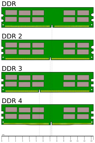
The naming of DDR memory modules can be confusing at first glance. For example, a stick labeled DDR5-6000 (PC5-48000) tells you two things: the “DDR5-6000” part refers to the memory’s data rate: 6,000 megatransfers per second (MT/s), which is the effective speed at which data can be read or written. The “PC5-48000” part is the theoretical peak bandwidth in megabytes per second (MB/s), calculated as 8 times the data rate (6000 × 8 = 48,000 MB/s). So, DDR5-6000 (PC5-48000) means this module can transfer data at up to 6,000 MT/s, with a maximum bandwidth of 48 GB/s per channel under ideal conditions.
You may also see memory described by its CAS Latency (CL) and timings, such as CAS Latency 36 or 36-44-44-96. CAS Latency is the number of clock cycles between when the memory controller requests data and when it is available from the RAM. Lower CAS Latency means less delay, but actual performance depends on both latency and data rate. The full timing string (e.g., 36-44-44-96) refers to a sequence of delays for different memory operations:
- CAS Latency (CL): delay for column access
- tRCD: Row to Column Delay
- tRP: Row Precharge Time
- tRAS: Row Active Time
Lower numbers are generally better, but must be considered alongside the memory speed for real-world performance.
Desktop boards support generations like DDR4 or DDR5; you must match the memory to what the CPU/motherboard supports. Two sticks arranged for dual channel usually outperform a single larger stick because the memory controller can access two channels in parallel. Vendors publish memory profiles (XMP for Intel, EXPO for AMD) that set frequency and timing automatically; enabling them after a stable first boot yields the intended speed.
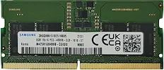
Laptop RAM (commonly called SO-DIMM) is physically smaller than desktop DIMMs and often operates at lower voltages to save power and reduce heat. For example, DDR4 laptop memory typically runs at 1.2V, while DDR5 SO-DIMMs may use even less. Always check both the form factor and voltage requirements when upgrading laptop memory, as using the wrong type or voltage can prevent the system from booting or cause instability.
Capacity planning follows workload: 16-32 GB for general use, 32-64 GB for heavy creative or virtualization tasks, and more for specialized servers.
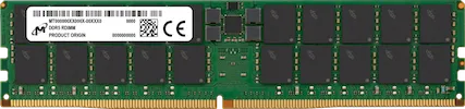
Error-Correcting Code (ECC) memory adds extra bits to detect and correct single-bit errors caused by cosmic rays or electrical noise. Most mainstream consumer desktops do not support ECC, though some AMD consumer platforms can use unbuffered ECC (also called ECC UDIMM, a standard desktop-style ECC module that connects directly to the memory controller without an extra register chip) if the CPU, motherboard, and firmware all support it. Workstation-class and server platforms are much more likely to support ECC officially, and servers often add support for Registered DIMMs (RDIMMs), which place a register buffer between the memory controller and the DRAM chips so the system can drive more modules and larger capacities reliably. If you are speccing a machine that will run unattended for long periods or store data that must not be silently corrupted, confirm ECC support in the CPU and motherboard documentation before purchasing. The server and data center lecture covers ECC in more depth.
Unified Memory Architecture (UMA) is found in SoC-based systems such as Apple M-series and AMD APUs, where the CPU and GPU share a single physical memory pool rather than having separate pools. Because there is no separate VRAM, data does not need to be copied between memory pools before the GPU can process it, which reduces latency and improves efficiency for graphics and AI tasks. The trade-off is that GPU workloads consume memory that would otherwise be available to the CPU, and since memory is soldered, total capacity is fixed at purchase.
A few configuration guidelines to follow for reliable performance:
- Install in the slots the manual marks for 2-DIMM operation to enable dual channel.
- Prefer matched kits (2×16 GB) over mixing brands or speeds.
- Enable XMP/EXPO only after a clean, stable POST at default settings.
Interfaces and Connectors
Section titled “Interfaces and Connectors”Every desktop or laptop computer exposes a variety of ports (physical connectors on the case or motherboard) that allow you to attach external devices and peripherals. These interfaces connect your system to monitors, storage drives, networks, input devices, and more.
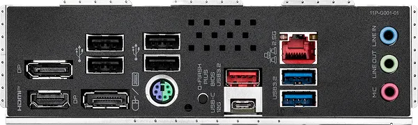
Understanding the difference between the protocol (the “language” and electrical signaling) and the physical connector (the mechanical shape) is key to predicting compatibility and performance. The arrangement and type of ports available will vary by system, but most computers include a mix of USB, audio, video, and networking connectors, along with specialized ports for storage and expansion.
Protocol vs. Physical Plug
Section titled “Protocol vs. Physical Plug”Many names you encounter (SATA, NVMe, PCIe, USB, Thunderbolt, M.2, DisplayPort) mix protocols (the “language” and electrical signaling) with physical connectors (the mechanical shape).
- M.2 is a connector specification that can carry different buses (PCIe, often for NVMe SSDs; SATA; or even USB), so an M.2 slot is not always NVMe-capable.
- NVMe itself is a storage protocol running atop PCIe, independent of the M.2 shape; the same protocol can use U.2/U.3 or add-in card form factors in servers.
- Thunderbolt encapsulates PCIe and DisplayPort plus power over a USB-C connector, demonstrating how a physical port can tunnel multiple protocols.
Distinguishing these layers helps you predict compatibility: a USB-C shaped port may only implement USB 2.0 internally, while a “Gen 2x2” port advertises both connector and high signaling rate.
SATA (Serial AT Attachment) replaced the older PATA (Parallel ATA) standard, which used wide ribbon cables. SATA uses thin, dedicated cables for both data and power, and is still common for HDDs and budget SSDs, though M.2/NVMe is now preferred for performance builds.
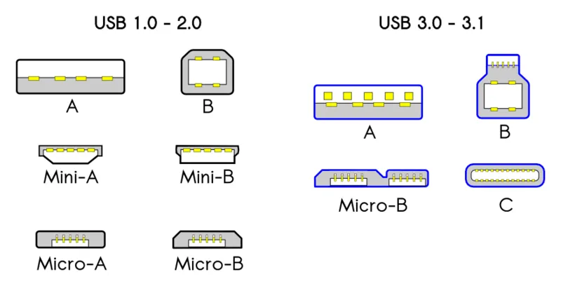
USB (Universal Serial Bus) is the predominant peripheral interface today. Generations differ significantly in speed:
| USB Version | Max Speed |
|---|---|
| USB 1.1 | 12 Mb/s |
| USB 2.0 | 480 Mb/s |
| USB 3.x | 5-20 Gb/s (Gen 1 / Gen 2 / Gen 2×2) |
| USB 4 / Thunderbolt | 20-80 Gb/s |
With USB 3.2 and USB 4, USB-C is the dominant connector for the newest high-speed modes, especially for USB4 and Thunderbolt. USB-A still exists on many systems for USB 3.x devices, but connector shape alone does not tell you the supported speed. Note that USB marketing names (e.g., “USB 3.2 Gen 2×2”) describe both speed tier and signaling mode; always verify the actual port, cable, and device capabilities when purchasing cables or hubs.
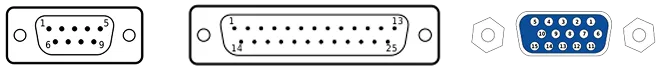
Legacy interfaces like RS-232 (serial) and VGA (analog video) persist for diagnostics and KVM (Keyboard-Video-Mouse) switches, which let one keyboard and monitor control multiple servers, even if they are no longer performance-relevant. They are another good example of how standards and physical connectors differ. RS-232 can use DE-9 or DB-25 connectors, while VGA uses a DE-15 connector even though early days also used DE-9.
The table below compares representative peak theoretical speeds of common interfaces. The assumptions matter: some rows are per lane, some are per link, and some are for a specific current-generation configuration. Real-world performance is always lower because of encoding overhead, protocol overhead, queue depth, signal quality, and device implementation. Use this as a quick comparison table, not as a substitute for reading the exact spec.
| Interface | Representative peak bandwidth | Assumption |
|---|---|---|
| SATA | 6 Gb/s | SATA III link |
| SAS | 24 Gb/s | SAS-4, per lane |
| NVMe SSD | 128 Gb/s | PCIe 5.0 x4 SSD link, bidirectional raw aggregate |
| PCI Express slot | 512 Gb/s | PCIe 5.0 x16 slot, one direction raw |
| USB4 / Thunderbolt | 80 Gb/s | USB4 v2 / Thunderbolt 5 peak mode |
| HDMI | 48 Gb/s | HDMI 2.1 FRL |
| Ethernet | 400 Gb/s | 400GbE link |
| Wi-Fi | 46 Gb/s | Wi-Fi 7 theoretical maximum, top-end configuration |
| Bluetooth | 3 Mb/s | Bluetooth Classic EDR class; BLE is lower |
| Cellular | 1 Gb/s | LTE Advanced Pro class, theoretical peak |
| DRAM | 384 Gb/s | DDR5-6000 dual-channel desktop memory, theoretical peak |
When selecting or configuring interfaces, keep these in mind:
- Read motherboard fine print for which M.2 keys (B, M, B+M) and protocols each slot supports.
- Treat USB marketing names (3.2 Gen 1/Gen 2/2x2) as bandwidth indicators, not just connector shape.
- Prefer DisplayPort (or USB-C Alt Mode) for high refresh, high resolution displays.
Verify electrical lane counts and protocol support before purchasing: an M.2 slot may be SATA-only, a USB-C port may be power-only or limited to low speeds, and an x16-length PCIe slot does not guarantee x16 electrical bandwidth.
Storage and Expansion Planning
Section titled “Storage and Expansion Planning”Building on interconnect concepts, storage and expansion planning combines media characteristics, connector/protocol capabilities, physical slot layout, and data integrity strategies.
While NVMe dominates performance discussions, multiple storage media remain relevant:
- Hard Disk Drives (HDDs) use spinning magnetic platters and moving heads, offering low cost per GB and good sequential throughput but higher latency and mechanical fragility;
- Solid-State Drives (SSDs) store data in NAND flash with no moving parts, giving very low seek latency and high parallel throughput;
- Optical media (e.g., Blu-ray) and tape provide removable or archival options with long shelf lives but slow random access.
SSD endurance is finite because flash cells wear after program/erase cycles; firmware spreads writes via wear leveling and recovers performance with TRIM, a command by which the OS signals which blocks are no longer in use so the drive can pre-erase them.
Both HDDs and SSDs expose SMART (Self-Monitoring, Analysis and Reporting Technology) attributes to predict some failure modes, but sudden failures still occur; data protection relies on backups and redundancy, not SMART alone. Failure rate curves commonly show early “infant mortality,” a stable middle period, then rising wear-out; burn-in testing can catch early defects.
Physical form factor governs slot count and layout (ATX vs. mATX vs. ITX) and interacts with lane sharing: adding a second NVMe drive may downshift a PCIe slot or disable SATA ports, so manuals matter.
Plan early so cable routing, thermals, and lane allocation reinforce rather than conflict.
When configuring storage, follow these guidelines:
- Use an NVMe drive for OS, apps, and I/O-intensive workloads, and optional SATA/HDD for bulk media or backups.
- Enable TRIM (modern OSes do this by default) to sustain SSD write performance.
- Monitor key SMART attributes (reallocated sector count, media errors) and act on trends, not isolated single values.
- Verify heatspreaders or board-side M.2 shields fit with your chosen drives.
- In small ITX builds, prefer single-sided M.2 SSDs and low-profile cables to reduce clutter.
Graphics and Parallel Accelerators
Section titled “Graphics and Parallel Accelerators”Graphics Processing Units (GPUs) evolved from fixed-function pipelines into massively parallel processors optimized for throughput on vectorizable workloads.
For desktops they render frames; for compute they accelerate machine learning, scientific simulation, and video transcoding. Performance depends on shader count, memory bandwidth, and driver/runtime stack; bottlenecks arise when feeding data across a limited PCIe link or from insufficient system RAM. A GPU can be bottlenecked by a slow CPU (the CPU cannot prepare draw calls or data fast enough) and conversely a very fast GPU may idle waiting on a weak CPU; this CPU-GPU imbalance is commonly called a “bottleneck” and is worth checking when selecting parts for gaming or compute builds.
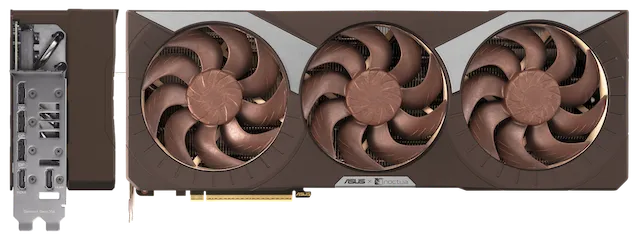
Integrated graphics share system memory and are power-efficient, while discrete GPUs offer higher performance at greater power and thermal cost. Emerging accelerators (TPUs, NPUs) specialize further, trading flexibility for efficiency on specific operations like matrix multiply or inference.
When selecting and installing a GPU or accelerator:
- Match GPU capability to resolution/refresh or compute workload; excess capacity wastes power.
- Ensure the PSU has sufficient dedicated PCIe power connectors and headroom.
- Consider case airflow (exhaust vs. axial cooler designs) to prevent hotspot recirculation.
Ensure the PSU has sufficient headroom before adding a second accelerator, and keep cable runs and drive cages clear of the GPU intake to prevent thermal throttling.
Power, Cooling, and Firmware
Section titled “Power, Cooling, and Firmware”All the components you have selected only deliver sustained performance when electrical power is stable, heat is removed efficiently, and low-level firmware is configured sensibly. In 2025, ATX 3.x power supplies are increasingly recommended for new builds with high-end GPUs because they are designed to tolerate larger transient loads cleanly.
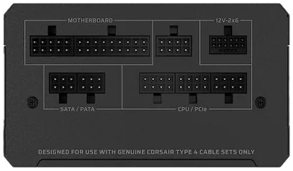
A power supply unit (PSU) converts wall AC into regulated DC rails and exposes the 24-pin ATX connector for the board, one or two 8-pin EPS connectors for CPU power, and PCIe leads for GPUs.
The ATX connector is the standard 24-pin plug that powers the motherboard; EPS is a similar standard for CPU power. Choose wattage by adding the realistic maximum draw for CPU and GPU, then adding about 30-40% headroom to keep the PSU in an efficient, quiet range; favor reputable models with robust protections and an 80 Plus rating. Modular PSUs make upgrades and repairs easier, reducing e-waste.
Cooling keeps components within safe temperature limits; tower air coolers and AIO (All-In-One) liquid coolers must fit the case and memory height, and case fans should create a front/side-to-rear/top airflow path. PCIe 5.0 and Gen5 NVMe SSDs can run hot; ensure adequate airflow or heatsinks for these devices. When possible, choose fans and coolers that are easy to clean and replace, supporting longer hardware lifespans. Mount AIO radiator tubes at the bottom of a front intake to avoid trapping air in the pump head; also verify cooler height against the tallest RAM sticks before purchase.
Firmware is the low-level software that runs before your operating system. Modern systems use UEFI (Unified Extensible Firmware Interface), which replaces the older BIOS. UEFI provides a graphical setup menu, lets you configure fan curves, memory profiles (XMP/EXPO), Secure Boot, Trusted Platform Module (TPM) settings, and hardware virtualization extensions. These extensions, called VT-x on Intel platforms and AMD-V on AMD platforms, let the CPU execute multiple isolated operating systems simultaneously with minimal overhead. Their Input-Output Memory Management Unit (IOMMU) counterparts (Intel VT-d, AMD AMD-Vi) extend that isolation to I/O devices, allowing a hypervisor to pass a physical NIC or GPU directly to a guest. On many consumer boards these flags ship disabled by default; a hypervisor will either refuse to start or fall back to much slower software emulation without them. Enabling them in UEFI before installing a hypervisor is the first configuration step the virtualization lecture will build on. With good power, clean airflow, and sensible firmware settings, you get a system that is fast, quiet, and reliable.
For reliable, efficient operation:
- Use separate PCIe power cables for high-draw GPUs instead of daisy-chaining splitters.
- Start with conservative fan curves, then tune for noise vs. temperature after stress testing.
- Update firmware only on a stable system and only when it solves a real issue.
- Prefer modular, repairable PSUs and coolers to reduce e-waste and support sustainability.
Enterprise and Business-Grade Hardware
Section titled “Enterprise and Business-Grade Hardware”Consumer and business-class components share the same fundamental architecture but diverge in several areas relevant to system administrators. Business-grade and enterprise hardware typically includes:
- Remote management features such as Intel vPro and AMD PRO platforms, which allow IT staff to remotely power cycle, update firmware, or diagnose systems even when the OS is unresponsive or the machine is powered off.
- Hardware security add-ons: hardware-backed encryption keys, firmware integrity verification, and platform attestation features built into the CPU and chipset.
- Extended warranty and service contracts: consumer-grade drives typically carry 2-5 year warranties; enterprise drives often have 5-year warranties and rated duty cycles suited for 24/7 operation.
- ISV (independent software vendor) certifications: workstations from Dell, HP, and Lenovo with certified drivers for CAD, medical imaging, or financial software.
The practical implication is that enterprise platforms simplify large-scale deployments and reduce the cost of unplanned downtime, but carry a price premium. For a sysadmin, understanding these features helps justify hardware selection to stakeholders and enables faster troubleshooting through remote management tooling.
Hardware Repairs, Diagnostics, and Tools
Section titled “Hardware Repairs, Diagnostics, and Tools”Knowing how to diagnose and repair hardware is a core sysadmin skill. Before ordering replacement parts or escalating to a vendor, run systematic diagnostics.
Repair guidance
- iFixit maintains free, community-sourced teardown and repair guides for thousands of consumer devices. Search by model (e.g., “HP EliteBook 840”) to find step-by-step instructions and identify replaceable components.
- Manufacturer documentation (Dell, HP, Lenovo, etc.) provides service manuals and parts lists for business hardware.
Per-OS diagnostic entry points
- macOS: Run Apple Diagnostics at startup; review logs in the Console app.
- Windows: Use Performance Monitor, Windows Memory Diagnostic, and
chkdskfor disk checks. - Linux: Review
dmesg, kernel logs in/var/log, and the Red Hat hardware troubleshooting guide.
Diagnostic tools
| Tool | Purpose |
|---|---|
| MemTest86 | Bootable memory stress test (x86 and ARM) |
| Prime95 | CPU stability and thermal stress test |
| smartmontools / S.M.A.R.T. | Drive health monitoring (HDD and SSD) |
| AIDA64 | System information, hardware sensor monitoring, stability tests |
| Vendor tools | Most server vendors (Dell iDRAC, HP iLO) ship their own diagnostic suites |
General approach: check logs, note any diagnostic LED codes or beep codes at POST, measure temperatures and utilization, inspect for physical damage and loose connections, then use the tools above to isolate the failing component. Always start by verifying the basics (power, seating, and connections) before running software diagnostics.
Assembly To First Boot
Section titled “Assembly To First Boot”With parts chosen for compatibility, careful physical assembly and a disciplined first-boot process convert planning into a working machine.
Building a computer is a process where careful planning and methodical steps pay off. The goal is to assemble the system so that every part is properly installed, cables are tidy, and the system boots reliably on the first try. The process starts with a “breadboard” test outside the case, then moves to final assembly, and ends with a first boot validation. Following a clear sequence helps avoid common mistakes and makes troubleshooting much easier if something goes wrong. Observe basic electrostatic discharge (ESD) precautions (work on a non-conductive surface and touch grounded metal before handling components) to reduce the chance of latent damage.
-
Breadboard Test (Outside the Case)
Install the CPU, one stick of memory, and (if needed) the GPU on the motherboard outside the case. Connect the power supply and monitor. Power on to check for a successful POST (Power-On Self-Test) and display output. This step ensures your core parts work before you commit to full assembly.
-
Install in the Case
Mount the motherboard on the correct standoffs, install the I/O shield if needed, and route the main power cables (24-pin ATX, 8-pin EPS for CPU). Connect front-panel connectors (power switch, reset, LEDs) as shown in the manual. Install storage drives and any additional cards.
-
Cable Management and Final Checks
Tidy up cables to ensure good airflow and no loose connectors. Double-check that all power cables are fully seated and that no standoffs are misplaced under the board (which could cause a short).
-
First Boot and UEFI Setup
Power on the system. Enter UEFI/BIOS to confirm that the CPU, memory, and drives are detected. Check idle temperatures. Only after a clean POST should you enable memory profiles (XMP/EXPO), set the boot order, and adjust fan curves. If there is no display or no POST, simplify the build, reseat memory and GPU, and consult the board’s diagnostic LEDs or beep codes.
Takeaways
Section titled “Takeaways”The lecture traces a path from the platform decision outward through every other constraint. Choosing a CPU and motherboard locks in the socket, the memory generation, and the primary PCIe lanes; every later choice must fit inside that envelope. The case and form factor then enforce the physical limits: cooler height, GPU length, radiator mounting, and cable routing all become first-class variables that interact with thermals. Memory must be installed in the right slots for dual-channel operation, and its rated speed is only realized after enabling XMP or EXPO in UEFI. Storage planning requires reading the board manual carefully because NVMe slots share lanes with PCIe or SATA connectors in ways that are not visible from the slot count alone. The PSU must cover realistic peak draw with headroom, and the firmware must be configured deliberately rather than left at factory defaults.
To see how these layers interact in practice, consider spec-ing a machine for virtualization workloads. You start by confirming that the CPU supports hardware virtualization extensions (VT-x or AMD-V) and that the board supports ECC memory, both verified in the CPU and motherboard documentation before purchase. You select a case and cooler combination that can sustain continuous load without thermal throttling, noting the cooler height limit against your memory sticks. You populate ECC UDIMMs in the dual-channel slots the manual specifies, then enable EXPO after a clean first boot. You verify that the M.2 slot you need for the OS drive does not disable a SATA port you depend on for secondary storage. Before installing any software, you run a memory test, check temperatures under synthetic CPU load, and take a SMART baseline on every drive. Only after all of that do you enable the virtualization extensions in UEFI and install a hypervisor.
That preparation is the difference between a server that runs reliably for years and one that fails silently at an inconvenient hour. A premium memory kit left at default speeds looks like a capacity problem but is a configuration problem. A PSU running near its rated maximum heats the case and shortens component life. An M.2 slot sharing lanes with the GPU shows up as a storage bottleneck only under mixed workloads. Knowing the hardware layer well enough to catch these issues before they become incidents is what makes the difference between reactive and preventive administration. The next lecture on virtualization picks up exactly where this one leaves off: with a stable physical platform and hardware virtualization extensions enabled in UEFI, you will see how a hypervisor divides that single machine into multiple isolated guests.
Resources
Section titled “Resources”- Crash Course Computer Science #6: Registers and RAM (YouTube)
- Crash Course Computer Science #7: The CPU (YouTube)
- Crash Course Computer Science #9: Advanced CPU Designs (YouTube)
- Motherboard Parts and Their Functions (Tom’s Hardware)
- Troubleshooting hardware problems in Linux (Red Hat Enable Sysadmin)