Cisco Packet Tracer: Small Enterprise Network
This activity puts into practice the concepts from the Networking Fundamentals (LAN/WAN) and Network Configuration and Troubleshooting lectures. You will build a small enterprise network step by step in Cisco Packet Tracer, configuring VLANs, inter-VLAN routing via a multilayer switch, DHCP, and wireless access. By the end, you will have connected all device types on a segmented network and seen how each layer of the design addresses a specific networking concern.
What You Will Need
Section titled “What You Will Need”- Cisco Packet Tracer installed (download from netacad.com after creating a free account)
- About 60-90 minutes
The Interface
Section titled “The Interface”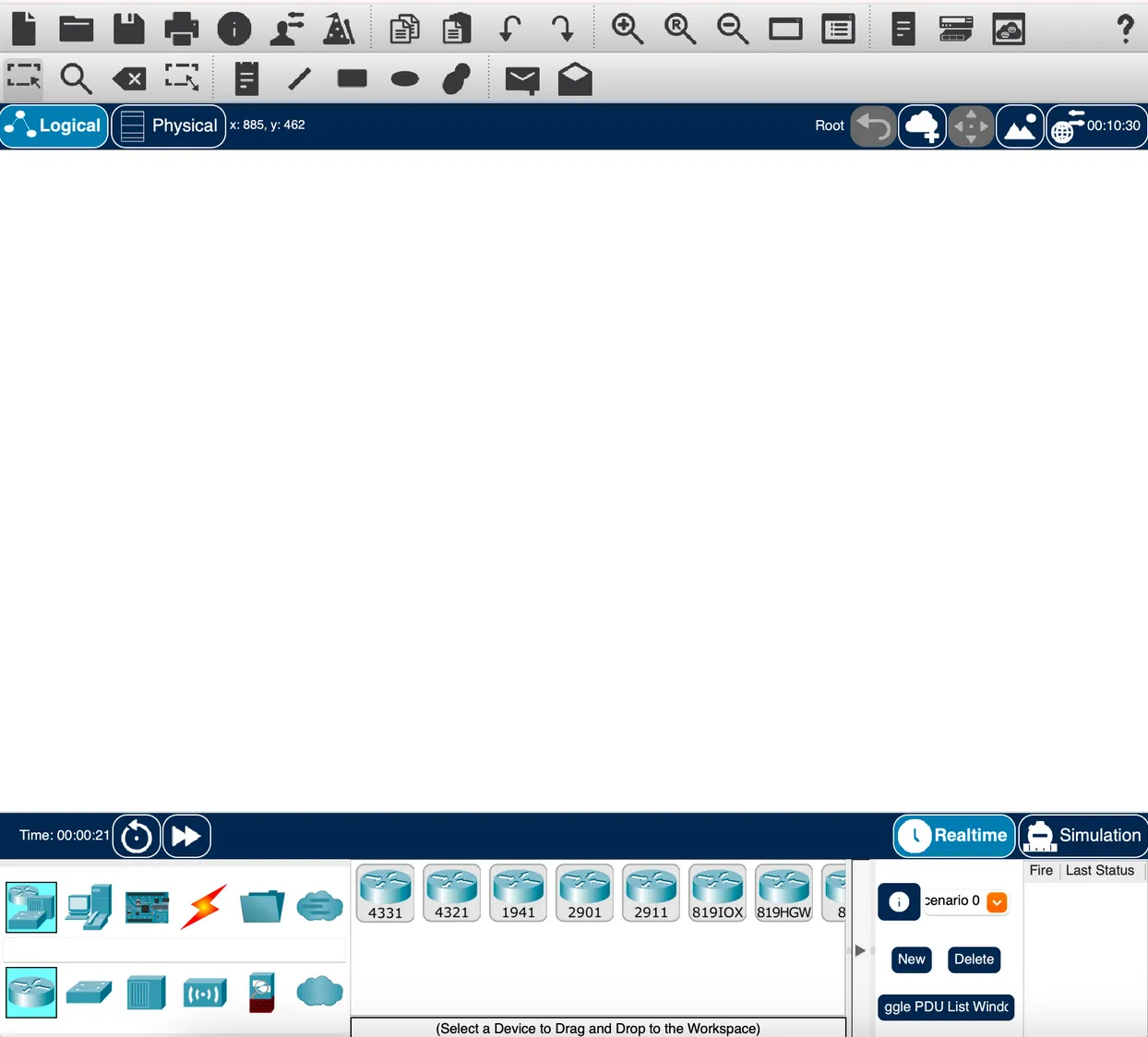
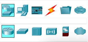
Adding Devices
Section titled “Adding Devices”In the bottom-left corner, the first row shows device categories. Clicking a category updates the second row with specific models. Use the search field between the rows to find a device by name.
Once you select a category, the device list updates on the right:
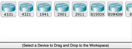
Click a device, then click the canvas to place it, or drag and drop. For cables, click the cable type, then click the first device and choose a port. Selecting Automatically Choose Connection Type handles cable type and port for you.
Canvas and Simulation Modes
Section titled “Canvas and Simulation Modes”The canvas has a logical view (where you will spend most of your time) and a physical view (a rack/map view). There are two simulation modes:
-
Realtime: Devices power on and behave like real hardware. Links start orange while devices negotiate; click the fast-forward button to advance time. A red link means a misconfiguration.

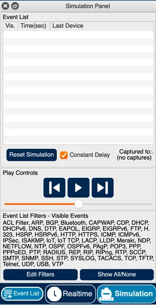
-
Simulation: Step through network events one at a time. Filter the event list to the protocols you care about (ARP and ICMP are a good starting point for this activity).
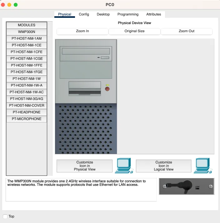
Interacting with Devices
Section titled “Interacting with Devices”Click any device to open its panel. The tabs you will use most:
-
Physical: Power the device on or off; add or swap hardware modules (the device must be off to change modules).
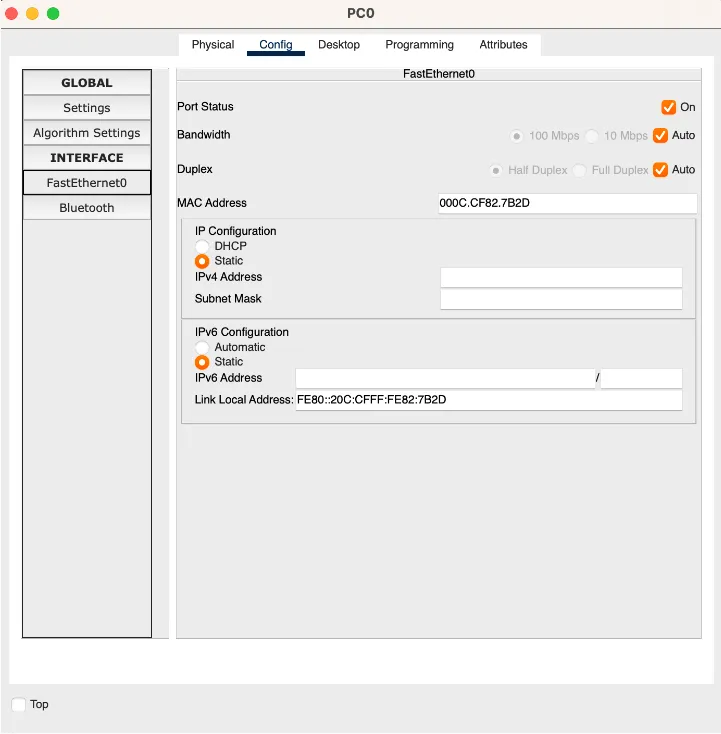
-
Config: Configure global settings and interfaces using a graphical form.
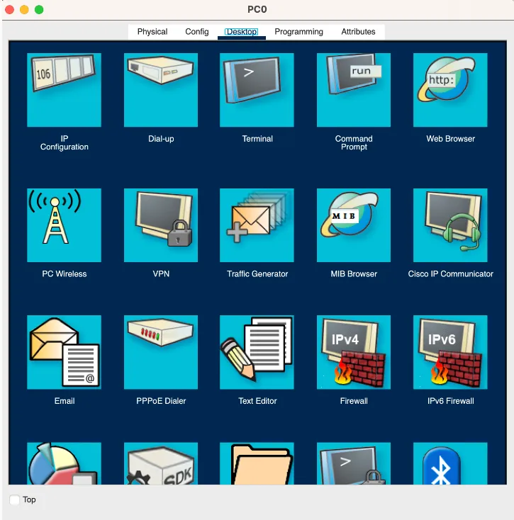
-
Desktop (PCs and end-user devices): Run Command Prompt, Web Browser, and IP Configuration.
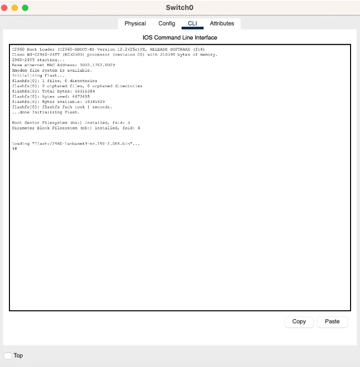
-
CLI (switches, routers, multilayer switches): Full IOS command-line interface.
Part 1: VLAN Setup
Section titled “Part 1: VLAN Setup”Lecture concept: VLANs and network segmentation (Network Configuration and Troubleshooting). VLANs partition a single physical switch into multiple isolated broadcast domains. Here you will create two VLANs representing two departments and assign switch ports to them.
-
Add five PCs to the canvas:
PC0,PC1,PC2,PC3,PC4. -
Add two access switches (model 2960):
access-SW0andaccess-SW1. ConnectPC0,PC1, andPC2toaccess-SW0via straight-through cables (FastEthernet ports, starting fromFa0/1). ConnectPC3andPC4toaccess-SW1the same way. -
Add a distribution switch (model 2960):
dist-SW. Connect it to each access switch using crossover cables on the GigabitEthernet ports of the access switches and FastEthernet ports on the distribution switch. -
Assign IP addresses to the PCs. Use two subnets for the two departments:
- 192.168.10.0/24 for SALES
- 192.168.20.0/24 for FINANCE
On each PC: click the PC, go to Desktop > IP Configuration, and enter the IPv4 address and subnet mask (255.255.255.0).
-
Open a Command Prompt on
PC0and try pingingPC1(same subnet) andPC4(different subnet). Note the results before continuing. -
Configure VLANs on all three switches. On each switch, open the CLI tab and run:
enconf tvlan 10name SALESvlan 20name FINANCEexitexitshow vlan -
Assign each access port to the correct VLAN. On each access switch, open the Config tab, select the interface connected to each PC, and set the VLAN. You can also do this from the CLI:
interface FastEthernet0/1switchport access vlan 10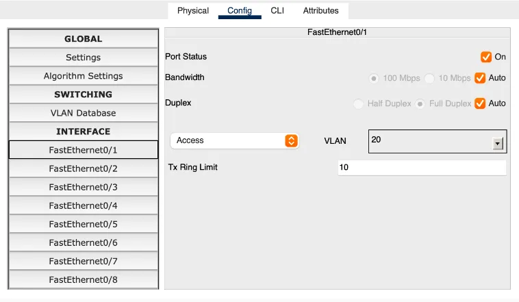
-
Set the uplink ports connecting the access switches to the distribution switch to trunk mode in the Config tab. The remote end updates automatically.
Part 2: Inter-VLAN Routing
Section titled “Part 2: Inter-VLAN Routing”Lecture concept: Routing Basics (Networking Fundamentals) and VLANs and network segmentation (Network Configuration and Troubleshooting). Layer 2 switches forward frames within a VLAN but cannot route between them. A multilayer switch (MLS) adds Layer 3 routing and uses Switch Virtual Interfaces (SVIs) to provide a default gateway per VLAN.
-
Add two more VLANs to all three switches:
- 192.168.99.0/24 for MANAGEMENT
- 192.168.200.0/24 for WIFI
-
Add a multilayer switch (model 3560, the MLS) to the canvas. Connect it to
dist-SWusing the correct cable, set both ports to trunk mode, and add all four VLANs to the MLS. -
Configure a Switch Virtual Interface (SVI) for each VLAN on the MLS. In the CLI:
interface vlan 10ip address 192.168.10.1 255.255.255.0Repeat for VLANs 20, 99, and 200 with the correct subnet. Then enable IP routing:
ip routingVerify with
show run. -
Set the default gateway on each PC to
192.168.x.1(the SVI for its VLAN). Open each PC, go to Desktop > IP Configuration, and fill in the Default Gateway field.Now repeat the ping test from Part 1, Step 5.
PC0should now be able to reachPC4.
Part 3: Static Routing to a Border Router
Section titled “Part 3: Static Routing to a Border Router”Lecture concept: Routing Basics (Networking Fundamentals). Static routes are manually configured paths used when there is a small number of routes or when you need predictable, controlled forwarding behavior. Here you will connect the MLS to an upstream router and configure static routes on both devices.
-
Add a router (model 4331) to the canvas. Connect it to the MLS with the appropriate cable.
-
On the router, open the Config tab, power on the connected interface, then set:
- IPv4 Address: 172.16.1.1
- Subnet Mask: 255.255.255.252
-
On the MLS, disable switching on the port connected to the router (converting it from a Layer 2 switch port to a Layer 3 routed port):
interface GigabitEthernet0/2no switchportip address 172.16.1.2 255.255.255.252 -
Add static routes on both devices:
ip route 0.0.0.0 0.0.0.0 GigabitEthernet0/2 (on the MLS)ip route 192.168.0.0 255.255.0.0 GigabitEthernet0/0/0 (on the router)
Part 4: DHCP
Section titled “Part 4: DHCP”Lecture concept: Core Network Services: DNS, DHCP, and NAT (Networking Fundamentals) and DHCP: dynamic addressing (Network Configuration and Troubleshooting). DHCP eliminates manual IP assignment by having clients request an address from a server. When the DHCP server is on a different subnet, a relay agent (ip helper-address) forwards the broadcast to the server’s unicast address.
-
Add a server to the canvas. Connect it to the MLS and set the port to Access VLAN 99 (Management).
-
On the server, configure a static IP:
- IPv4 Address: 192.168.99.100
- Subnet Mask: 255.255.255.0
- Default Gateway: 192.168.99.1
- DNS Server: 8.8.8.8
-
In the server’s Services > DHCP tab, turn the service On. Add a pool for VLAN 10:
- Pool Name: VLAN10-Pool
- Default Gateway: 192.168.10.1
- DNS Server: 8.8.8.8
- Start IP Address: 192.168.10.200
- Subnet Mask: 255.255.255.0
- Maximum Users: 50
Click Add. Repeat for VLAN 20 with the corresponding values.
-
Add a DHCP relay helper on the MLS so VLAN clients can reach the server across subnet boundaries:
interface vlan 10ip helper-address 192.168.99.100Repeat for VLAN 20.
-
Add two new PCs. For each one:
- Connect it to an access switch and set the port VLAN.
- Open the PC, go to Config, and set the IPv4 source to DHCP.
Fast-forward and verify the PCs receive addresses in the expected range.
Part 5: Wireless
Section titled “Part 5: Wireless”Lecture concept: Wi-Fi fundamentals (Network Configuration and Troubleshooting). Enterprise wireless uses a Wireless LAN Controller (WLC) to manage multiple lightweight access points (LAPs) centrally, rather than configuring each access point independently.
-
Add a Wireless LAN Controller (WLC 3504) to the canvas. Connect it to the MLS and set the port to Access VLAN 99.
-
Configure the WLC’s management IP:
- IPv4 Address: 192.168.99.101
- Subnet Mask: 255.255.255.0
- Default Gateway: 192.168.99.1
- DNS Server: 8.8.8.8
-
Fast-forward, then from any wired PC open the Web Browser and navigate to
http://192.168.99.101. -
Create an admin account. In the setup wizard, confirm the management IP settings and proceed to Create Your Wireless Networks. Choose a network name (SSID) and WPA2 passphrase. Click through and apply. The WLC reboots.
-
While the WLC reboots, add a DHCP pool on the server for VLAN 200 (Wifi), starting at 192.168.200.100, with the WLC address (192.168.99.101) entered in the WLC Address field. Add a DHCP relay on the MLS for VLAN 200.
-
Add two lightweight access points (LAP-PT) to the canvas. Connect them to any switch and set the ports to VLAN 200. In each LAP’s Physical tab, drag the power cord to the power socket.
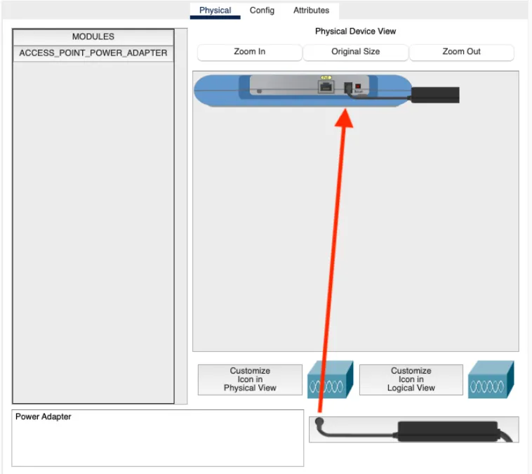
Set each LAP to DHCP in the Config tab. Fast-forward until they receive IP addresses.
-
Log back in to the WLC at
https://192.168.99.101(note the S). Go to WLANs > AP Groups, create a group calledLAP, add the SSID under WLANs, and add both access points under APs. -
Add one or two wireless devices (tablets, smartphones, or laptops). In the device’s Config tab, enter the SSID, enable WPA2-PSK, and enter the passphrase. Fast-forward and verify the device connects to one of the LAPs.
Verify Your Understanding
Section titled “Verify Your Understanding”Here is how each part of this activity maps to the lectures:
| What you did | Lecture section |
|---|---|
| Assigned PCs to subnets and observed broadcast isolation | IP Addressing and Subnetting; VLANs and network segmentation |
| Created VLANs and assigned ports | VLANs and network segmentation |
| Added trunk ports between switches | VLANs and network segmentation |
| Configured SVIs and enabled IP routing on the MLS | Routing Basics |
| Set default gateways on endpoints | Routing Basics |
| Added a /30 point-to-point link to a border router | IP Addressing and Subnetting; Static IP routing |
| Deployed a DHCP server and relay agents | Core Network Services: DHCP; DHCP: dynamic addressing |
| Connected wireless devices through a WLC and LAPs | Wi-Fi fundamentals; Enterprise wireless security |
Consider the following questions:
- Broadcast domains: Before configuring VLANs, all five PCs were on the same switch. What would happen if PC0 sent an ARP broadcast? After VLANs, what changed?
- Trunk ports: Why do the uplinks between switches carry all VLANs instead of just one? What would break if you set those ports to access mode for VLAN 10?
- MLS vs. external router: You used a multilayer switch for inter-VLAN routing instead of connecting each VLAN to a separate router interface. What are the trade-offs between these two designs?
- DHCP relay: The DHCP server is on VLAN 99 but serves clients on VLANs 10 and 20. Why does a relay agent work here when a simple broadcast would not reach across subnets?
- WLC vs. standalone APs: In the enterprise wireless setup, the WLC manages both LAPs centrally. What operational advantages does this provide over configuring each access point independently?
- Static vs. dynamic routing: You configured static routes between the MLS and the border router. Under what circumstances would you prefer a dynamic routing protocol (like OSPF or BGP) instead?